|
<< Click to Display Table of Contents >> Creating a Cross Section |
  
|
|
<< Click to Display Table of Contents >> Creating a Cross Section |
|
![]()
A new cross-section can be created by:
•selecting File > New > Cross Section
•clicking on the New button on the Main toolbar and selecting Cross-Section
•clicking on the New Cross-Section button
After this the New Cross-Section toolbar will then be displayed.
![]()
The buttons on this toolbar are used to perform the following tasks:
The Line button is used draw the pathline of the cross-section on the location map. When this button is pressed the cursor will change to cross-hairs and you will be able to draw the pathline. The drawing of pathlines is described in the section below.
The Path Width is used to specify the width of the pathline to use when selecting intersecting wells/boreholes.
The Ok button is used to complete the pathline entry and create the cross-section.
The Cancel button is used to abort the creation of the cross-section. When it is pressed the toolbar will disappear.
Drawing Path Lines
The pathline of the cross-section can be drawn by pressing the Line button on the toolbar. The cursor will then change to a “cross-hair”. Click on the location of the starting point of the cross-section and then click on each point of the pathline. Only the points where the pathline bends need to be clicked. At the last point on the path line double-click the mouse.
The Path Width represents the maximum distance a well can be from the pathline to be included in the cross-section. The selected wells will be highlighted as specified with the Symbols button. To increase the number of wells selected increase the Path Width.
After the desired pathline and wells have been selected, the cross-section can be created by pressing the Ok button.
When specifying the start and end of the pathline it should be noted that these points are also used to determine the distance between the edge of the cross-section and the first and last Borings/Wells. It is recommended that the start and end points be placed a little past the first and last Borings/Wells of the cross-section.
Specifying the Cross-section Name
After the pathline has been specified and the Ok button pressed, the New Cross Section Name form will be displayed.
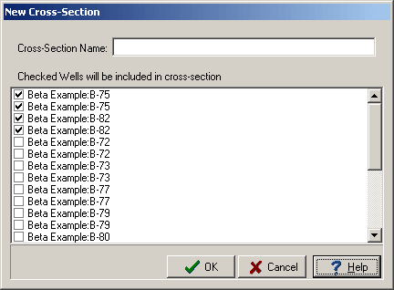
This form displays a list of current cross-sections in the project. Enter a unique name for the cross-section and then press the Ok button.
Selecting the Style
Next a style needs to be selected for the cross-section. After the Ok button on the New Cross Section Name form has been pressed, the Select Cross-section Style form will be displayed.
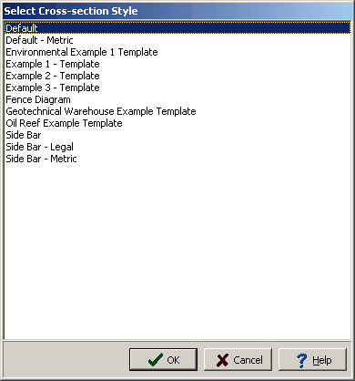
Select the style to use and then press the Ok button. The new cross-section will then be displayed. This cross-section can be edited and saved as described in the Editing a Cross-section below.
Auto Generation of Strata
The program can automatically generate the strata for the cross-section. This is done using artificial intelligence (AI) built-into the program. When determining how to connect the strata between Borings/Wells and intersecting cross-sections the program looks at the similarities in the lithologies, thicknesses, and occurrence of the strata. This methodology works well with most geologies; except, where the geology is very complicated or there are faults. In addition, the program’s AI will not be able to determine mineralization zones, hydrocarbon zones, contamination zones and alteration zones. However, these zones can be added and the strata can be edited after the cross-section has been generated.
The auto generation of the cross-section can be turned on and off on the Cross-sections tab in the program’s Preferences.