|
<< Click to Display Table of Contents >> Data Entry |
  
|
|
<< Click to Display Table of Contents >> Data Entry |
|
Open the Examples project and open Case 1.
General Tab
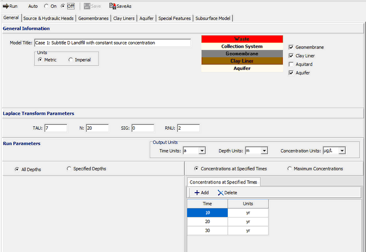
On the General tab, the title and layers present in the model are specified as shown above. In this example there is a geomembrane, clay liner and aquifer. At the bottom of the tab the run parameters can be specified. The concentrations can either be calculated at specified times or the time of the maximum concentration can be found.
Source & Hydraulic Heads Tab
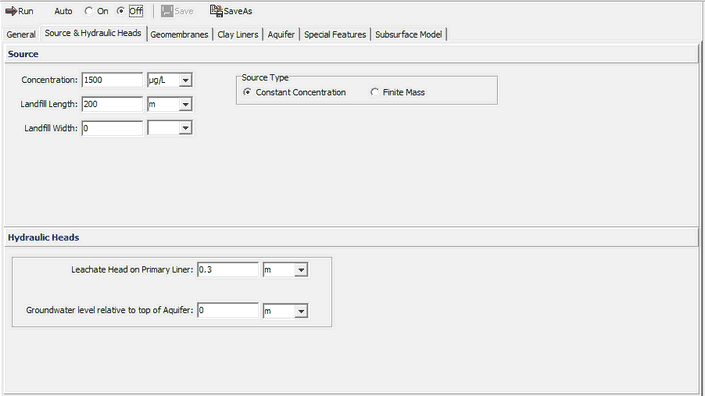
On this tab the Source Type, Source Concentration and Landfill Length are specified. In this example, the source type is constant concentration. If the source type was finite mass additional information for the source would need to be entered as discussed in Case 4.
The Hydraulic Heads is used to specify the leachate head on the primary liner and the groundwater level relative to the top of the aquifer. These heads are used to calculate the Darcy velocity through the liner.
Geomembranes Tab
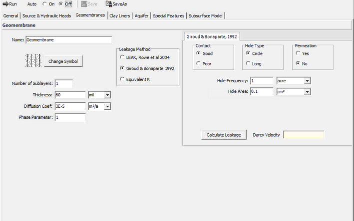
On this tab the Name, Thickness, Diffusion Coefficient, Phase Parameter, and method to calculate the leakage through the geomembrane is specified. If the method is Rowe et. al. 2004 or Giroud & Bonaparte 1992, an additional tab will be displayed to enter the hole parameters. If the method is equivalent K, then the Hydraulic Conductivity of the geomembrane can be entered on this tab. In this example the leakage method used is Giroud & Bonaparte 1992. Using this method the parameters for the holes in the geomembrane are specified. These parameters include the Type of Contact, Hole Type, Use of Permeation, and Hole Frequency. If the type of holes is Circles then the Hole Area can be specified, if the type is Long then the Hole Length and Width can be specified.
At the bottom of the tab, the Calculate Leakage button can be used to calculate and display the Darcy velocity (leakage) through the primary liner.
Clay Liners Tab
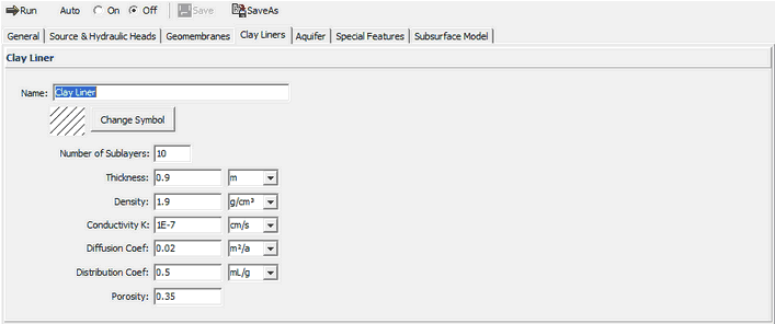
The Clay Liners tab below is used to specify the properties of the clay liner below the geomembrane. These properties include the Name, Symbol, Thickness, Density, Hydraulic Conductivity, Diffusion Coefficient, Distribution Coefficient, and Porosity.
Aquifer Tab
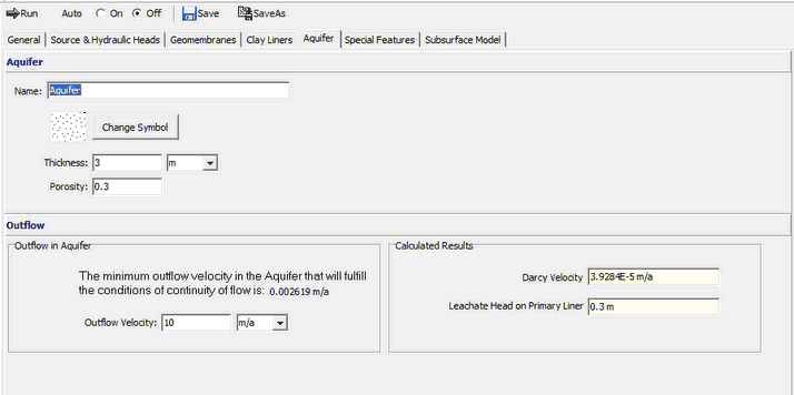
The Aquifer tab is used to specify the Name, Symbol, Thickness and Porosity of the Aquifer. At the bottom of the tab the Outflow Rate in the Aquifer can be specified. This rate should be at greater than or equal to the minimum calculated by the program. In this example, the minimum is 0.002619 m/a.