|
<< Click to Display Table of Contents >> Boundaries |
  
|
|
<< Click to Display Table of Contents >> Boundaries |
|
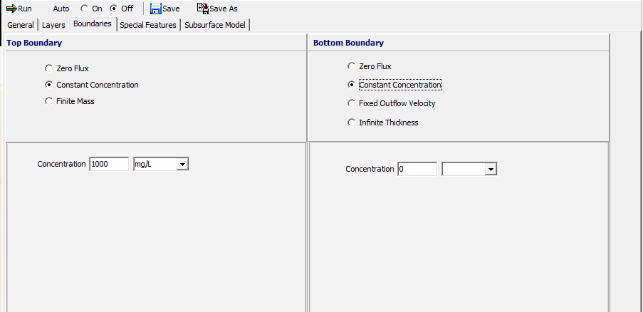
For every model there are two boundary conditions, one at the top and one at the bottom. The top boundary condition is usually the point of contact between the contaminant source (eg. a landfill) and the subsurface layers (deposit), and can be either:
•Zero Flux,
•Constant Concentration, or
•Finite Mass
The bottom boundary condition is usually the point of contact between the deposit and either a much more or much less permeable strata (eg. an aquifer or bedrock) and can be either:
•Zero Flux,
•Constant Concentration,
•Fixed Outflow, or
•Infinite Thickness
To edit the boundary data for a model click on the Boundaries tab on the left side of the model form.
Zero Flux Top Boundary Condition
The zero flux top boundary condition represents the case where there is no transmission of contaminant across the top boundary. This option is for highly specialized applications and is rarely used. If the top boundary is specified as zero flux no additional information is required.
Constant Concentration Top Boundary Condition
The constant concentration top boundary condition represents the case where the concentration of contaminant in the landfill remains constant throughout time, and is equivalent to the assumption of an infinite mass of contaminant in the landfill. If this top boundary condition is specified the following can be specified:
Concentration: This is the constant concentration for the top boundary.
Finite Mass Top Boundary Condition
The finite mass top boundary condition is most representative of a landfill, where the concentration of contaminant starts at an initial value, increases with time, and then declines as contaminant is transported into the subsurface and is removed by leachate collection systems.
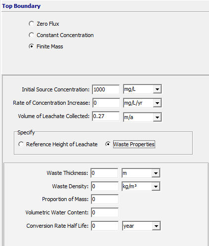
When the top boundary is finite mass the user must specify:
•Initial Source Concentration,
•Rate of Increase in concentration,
•Volume of Leachate Collected
and either:
•Thickness of Waste,
•Waste Density,
•Proportion of Mass,
•Volumetric Water Content of the waste,
•Conversion Rate Half-Life of the contaminant
or:
•Reference Height of Leachate
If the Variable Properties option has been selected from the Special Features menu, the values for the finite mass parameters will be specified in the Variable Properties entry instead.
Initial Source Concentration: This is the initial concentration of the source of contaminants, usually at time zero.
Rate of Concentration Increase: This is the rate of increase in concentration with time due to increasing mass entering the landfill. If the peak concentration is reached early in the landfill’s life and the analysis starts at this time, the rate of increase would be zero.
Volume of Leachate Collected: This is the volume of leachate collected per unit area of landfill per unit time, usually by the leachate collection system. Thus, the average volume of leachate collected is equal to the average infiltration through the landfill cover less the average exfiltration through the base of the landfill (assuming the waste is at field capacity). For example, if the average infiltration is 0.3 m/a and the average exfiltration is 0.03 m/a, then the average volume of leachate collected is 0.3-0.03 = 0.27 m/a.
Waste Thickness: This is the vertical thickness of the waste, and is used to calculate the mass of contaminant per unit area of waste. Either the thickness of waste or reference height of leachate must be specified.
Waste Density: This is the apparent density of the waste (i.e. mass of waste per unit volume of the landfill). Either the waste density or reference height of leachate must be specified.
Proportion of Mass: The available (leachable) mass of contaminant in the waste per unit mass of waste (eg. mass of chloride in waste/total mass of waste). Either the proportion of mass or reference height of leachate must be specified. Rowe et al (2004) report some published values for leachable mass.
Volumetric Water Content: This is the volumetric water content of the waste. Either the volumetric water content or reference height of leachate must be specified.
Conversion Rate Half-Life: The generation coefficient is calculated based on the conversion rate half-life K, such that = ln 2 / K. A value of = 0 implies no generation of concentration with time. In the program = 0 is obtained by specifying K = 0 (this is the default case).
Reference Height of Leachate: The reference height of leachate represents the volume of leachate that would contain the total leachable mass of a contaminant of interest at the initial source concentration. Thus, the reference height (Hr) is equal to the mass of contaminant (M) per unit area divided by the initial source concentration (co) (i.e. Hr = M/co).
Either the reference height of leachate or the waste thickness, waste density, proportion of mass, volumetric water content, and conversion rate half-life must be specified. If the reference height of leachate is zero then the mass of contaminant is calculated using the above parameters. If the reference height of leachate is not zero than the mass of contaminant is calculated using this value, and the above parameters are ignored. For example, if there is an average of 12.5 m of waste at a density of 600 kg/m3 and the contaminant represents 0.2% of the total waste mass, is then:
M = (0.2/100) (600) (12.5) = 15 kg/m2
And, if the initial source concentration is 1000 mg/L (i.e., 1 kg/m3) then the reference height is Hr = 15/1 = 15 m.
Zero Flux Bottom Boundary Condition
The zero flux bottom boundary condition represents the case where no mass is transported into or out of the bottom of the deposit. This condition can be used to represent the case of a deposit underlain by an impermeable base stratum (e.g., intact bedrock that is impermeable relative to the overlying layer or deposit). If the bottom boundary is specified as zero flux no additional information is required.
Constant Concentration Bottom Boundary Condition
The constant concentration bottom boundary condition represents the case where the concentration of contaminant remains constant in the base strata. The user will be prompted to specify the constant concentration in the base strata. If the bottom boundary condition is specified as constant concentration the following can be specified:
Concentration: This is the constant concentration for the bottom boundary.
Fixed Outflow Bottom Boundary Condition
The fixed outflow bottom boundary condition is most representative of the case where the model is underlain by an aquifer (permeable base strata). The concentration in the base strata (aquifer) varies with time as mass is transported into the aquifer from the deposit, and then transported away by the horizontal velocity in the base strata. The base aquifer is modelled as a boundary condition (not a separate layer) and the concentration at the bottom of the model is the concentration at the top of the base aquifer. This boundary condition assumes that there is sufficient dispersion/mixing such that the concentration is uniform across the thickness of the aquifer being considered. Thus the concentration at the bottom of the aquifer thickness modelled is the same as reported at the top of the aquifer. If the actual aquifer is very thick, normally only the upper portion (3 - 6 m depending on conditions) should be considered in modeling.
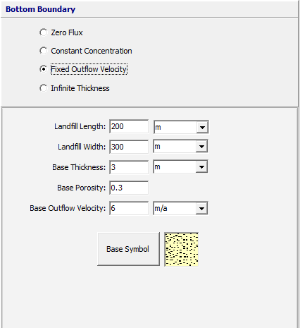
When the bottom boundary is specified as fixed outflow the following can be specified:
Landfill Length: This is the length of the landfill in the direction of groundwater flow.
Landfill Width: This is the width of the landfill in a direction perpendicular to groundwater flow. The width is usually set to 1, since it has no influence on the results.
Base Thickness: This is the vertical thickness of the base strata that is being modelled as a boundary condition.
Base Porosity: This is the porosity of the base strata, between 0 and 1.
Base Outflow Velocity: This is the horizontal Darcy outflow velocity within the base strata at the down-gradient edge of the landfill. If the outflow velocity is set very high the results will be equivalent to setting a constant base concentration of zero. If the Variable Properties option has been selected from the Special Features submenu, the value of the Outflow Velocity will be specified in the Variable Properties option.
Base Symbol: This is used to select the symbol that will be used for the aquifer when drawing the subsurface model. When the symbol is clicked on the symbol can be selected as described in the Select Symbol section.
Infinite Thickness Bottom Boundary Condition
The infinite thickness bottom boundary condition represents the case where the deposit extends infinitely in depth. This condition can be used to model lateral migration within the deposit. If the bottom boundary is specified as infinite thickness only the base symbol is required.
Base Symbol: This is used to select the symbol that will be used for the aquifer when drawing the subsurface model. When the symbol is clicked on the symbol can be selected as described in the Select Symbol section.