|
<< Click to Display Table of Contents >> Geomembranes |
  
|
|
<< Click to Display Table of Contents >> Geomembranes |
|
To edit the geomembrane data for a model click on the Geomembranes tab on the left side of the model form.
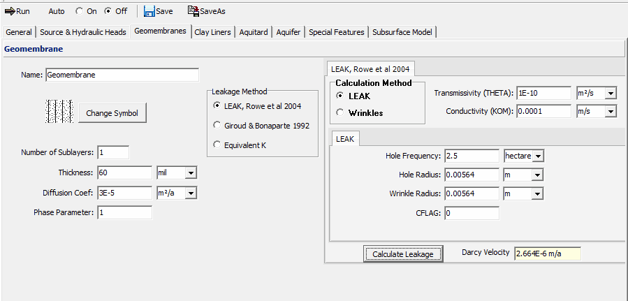
The following data can be edited on this tab:
Name: This is the name of the geomembrane layer.
Symbol: This is the symbol used to draw the geomembrane. To change the symbol click on the Change Symbol button. The Select Symbol form will be displayed where you can change the bitmap library, bitmap, foreground color, background color, and fill size for the symbol.
Number of Sublayers: This is the number of sublayers for the geomembrane and is typically 1.
Thickness: This is the thickness of the geomembrane.
Diffusion Coefficient: This is the diffusion coefficient of the geomembrane. See Rowe et al (2004) for a discussion of this parameter and a table of typical values.
Phase Parameter: This is a dimensionless phase parameter, ‘KH’ or ‘Sgf’, as discussed in the Introduction. The default is one; this represents no phase change. See Rowe et al (2004) for a discussion of this parameter and a table of typical values for common contaminants and HDPE geomembranes.
Leakage Method: This is used to select the method for calculating the leakage through the geomembrane. It can be calculated using the equations by Rowe et. al., 2004 for either a circular hole in a geomembrane in direct contact with the foundation (similar assumptions to Giroud but allowing one to consider more variables) or for a wrinkle (or series of wrinkles) with holes (the most realistic situation for many applications); Giroud & Bonaparte, 1992; or specifying an equivalent hydraulic conductivity.
LEAK, Rowe et at 2004
If the Leakage Type specified is Rowe et. al., 2004 the following can be specified:
Transmissivity (THETA): A detailed discussion of this is given by Rowe (1998) and the effect of this parameter is examined by Rowe et al (2004). Values used in examples include: 1.6x10⁻⁸ m2/s for “good contact” between a geomembrane (GM) and compacted clay liner (CCL), 1.x10-7 m2/s for “poor contact” between a GM and CCL, and 1.x10-10 m2/s for “typical” contact between a GM and geosynthetic clay liner (GCL).
Conductivity (KOM): This is the hydraulic conductivity of the collection system or other material directly above the hole in the geomembrane. The default is 1x10⁻⁴ m/s.
Calculation Method: The method used to calculate the leakage can be either: LEAK - a circular hole in a geomembrane in direct contact with the foundation (similar assumptions to Giroud but allowing one to consider more variables) or Wrinkles - for a wrinkle (or series of wrinkles) with holes (the most realistic situation for many applications).
Calculate Leakage: After all of the parameters have been specified, this button can be used to calculate and display the leakage (Darcy velocity) through the geomembrane.
LEAK
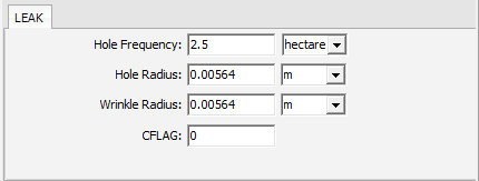
If the Calculation Method is selected as LEAK the following parameters can be specified:
Hole Frequency: This is the number of holes in the geomembrane per hectare or acre. The default is 2.5 holes per hectare. See Rowe et al (2004, Chapter 13) for a discussion of the number of holes per hectare.
Hole Radius: This is the average radius of the holes in the geomembrane. The default is 0.00564 m.
Wrinkle Radius: This is the optional average radius of the wrinkles in the geomembrane. The default is 0.00564 m. A "circular hole" can be either a wrinkle or a hole (both involve fluid in direct contact with the underlying clay liner. The only differences are (a) the wrinkle is bigger and (b) if it is a wrinkle then you also need a hole in the wrinkle and leakage through that hole can be controlled by Benoulli's equation).
CFLAG: This is either 1 or 0 depending upon the boundary. CFLAG is 1 when head in the underlying aquifer is greater than zero, and is 0 when the head is greater than the thickness of the soil layer above the
first aquifer.
Wrinkles
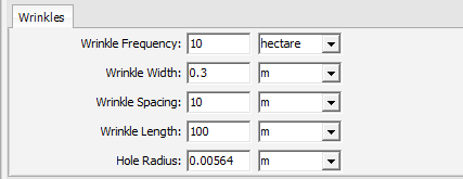
If the Calculation Method is selected as Wrinkles the parameters below can be specified. It is suggested that you sketch up the proposed idealized wrinkle configuration to make sure that it makes physical sense. It is easier to work in term of hectares and remember that a hectare is 100m by100m square. When modeling Wrinkles one is modeling those wrinkles that have holes. The frequency gives the number of wrinkles with holes per hectare (or acre) while the spacing and length give the typical wrinkle dimensions. For the default 10 (100m long) wrinkles/ha the spacing must by 10m (100m/no of wrinkles=10). For 5 (100m) long wrinkles the spacing would be 20m (100m/no of wrinkles=5). But if the wrinkles were only 20m long one could have 12 of them (three row of 4) with a spacing of 25m (100m/4 wrinkles per row).
Wrinkle Frequency: This is the number of wrinkles per hectare or acre. The default is 10 per hectare.
Wrinkle Width: This is the average width of the wrinkles. The default is 0.3 m.
Wrinkle Spacing: This is the average spacing between the wrinkles. The default is 10 m.
Wrinkle Length: This is the average length of the wrinkles. The default is 100 m.
Hole Radius: This the average radius of the holes in the wrinkles. The default is 0.00564 m. This will limit the leakage that can occur through a given wrinkle.
Giroud & Bonaparte 1992
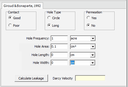
If the Leakage Type specified is Giroud & Bonaparte 1992 the following can be specified:
Contact: This is the type of contact between the geomembrane and the underlying material (either the clay liner or aquitard).
Hole Type: This is the type of holes in the geomembrane, either circles or long (rectangles).
Permeation: This is whether or not to consider permeation through the geomembrane.
Hole Frequency: This is the number of holes per hectare or acre. The default is 2.5 per hectare.
Hole Area: If the Hole Type is Circle then this parameter will be displayed. It is the average area of the holes in the geomembrane.
Hole Length: If the Hole Type is Long then this parameter will be displayed. It is the average length of the holes in the geomembrane.
Hole Width: If the Hole Type is Long then this parameter will be displayed. It is the average width of the holes in the geomembrane.
Equivalent K
Equivalent K: If the method used to calculate the leakage through the geomembrane is Equivalent K, then this parameter will be displayed. This is the equivalent hydraulic conductivity of the geomembrane. If you are unsure what the value of this is, it is recommended to use a leakage rate landfill. Note: that the use of an equivalent K is a device for convenience of calculation and in no way represents the true leakage mechanisms. We recommend that you use the leakage equations. See Rowe et al (2004) for a discussion of leakage equations.