|
<< Click to Display Table of Contents >> Components |
  
|
|
<< Click to Display Table of Contents >> Components |
|
The Components tab is used to enter the well components. These components consist of covers, caps, casings/screens, seals/packing, bottom seals, joints, and miscellaneous fittings.
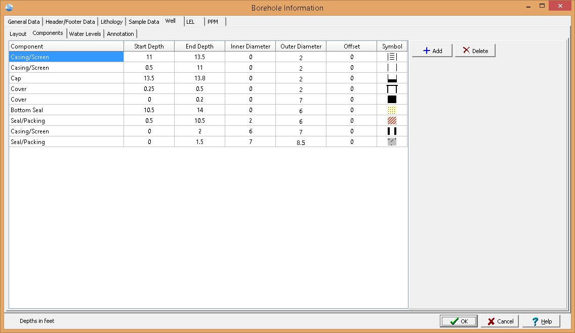
(The appearance of the form will differ slightly depending on if it is WinLoG or WinLoG RT)
The following information can be edited using this tab:
Component: This is the type of well component. When the cursor is clicked in this column, a combo box will be displayed. By clicking on the arrow to the right of this box, the type of component can be selected. The types of components that can be selected are Cover, Cap, Joint/Misc., Casing/Screen, Seal/Packing, and Bottom Seal.
Start Depth: This is the start depth of the component.
End Depth: This is the end depth of the component
Inner Diameter: This is the inner diameter of the component. It is only used for Seal and some Casing/Misc. components. These components will be drawn such that the shading and symbol patterns will fill the gap between the inner and outer diameters of the component. The components that use the inner diameter are discussed under the appropriate symbol at the end of this section.
Outer Diameter: This is the outer diameter of the component and is used by all of the types of components. The outer diameter must be less than the hole diameter. The width of the component inside the well column is determined by the ratio of the outer diameter and hole diameter. For example; if the outer diameter is 2 inches and the hole diameter is 8 inches, then the components width would be ¼ of the hole width.
Offset: This is the offset of the component from the center of the hole. Offsets to the left are negative and offsets to the right are positive. By specifying an offset to the component, multiple casings and piezometers can be placed within a single well column. For example; to specify two piezometers in a hole 10 inches in diameter. One piezometer could have an offset of –3 inches and the other piezometer could have an offset of 3 inches. The first piezometer would then be between 2 and 4 inches on the left side of the hole, and the second piezometer would be between 2 and 4 inches on the right side of the hole.
Symbol: This is the symbol to use for the component. The symbols available will vary depending upon the type of component. When the cursor is clicked inside this column one of the symbol forms described below will be displayed, depending on the type of component.
Cover
If the type of component is Cover then the Well Covers form will be displayed. Using this form the foreground color, line width, and symbol of the well cover can be selected.
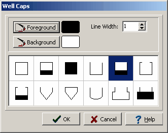
Cap
If the type of component is Cap then the Well Caps form will be displayed. This form is used to select the foreground and background colors, line width, and symbol for the cap.
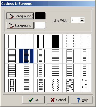
Casing/Screen
If the type of component is Casing/Screen then the Casings & Screens form will be displayed. This form is used to select the foreground and background colors, line width, and symbol for the casing or screen. If the inner diameter is specified, these symbols will fill the gap between the inner and outer diameter with the background color. Except for the third symbol, which will fill the gap with the foreground color.
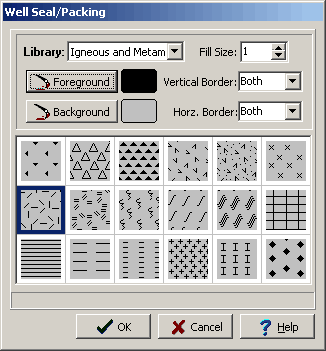
Seal/Packing
If the type of component is Seal/Packing or Bottom Seal then the Well Seal/Packing form will be displayed. This form is used to select the lithologic library, foreground and background colors, line width, vertical and horizontal borders, and symbol for the seal or packing. The line style used for the vertical and horizontal borders is set in the Layout tab. If the component is not a Bottom Seal and the inner diameter is specified, these symbols will fill the gap between the inner and outer diameter with the selected symbol. A Bottom Seal will fill everything between the outer diameter and any interior components with the selected symbol.
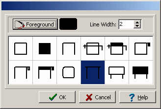
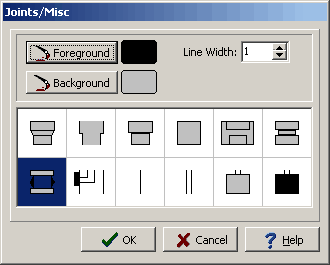
Joint/Misc.
If the type of component is Joint/Misc. then the Joints/Miscellaneous form will be displayed. This form is used to select the foreground and background colors, line width, and symbol. The first 6 symbols are used to represent couplings between pipes. All these couplings except for the 4th and 6th, will use the inner diameter as the bottom diameter of the connector. The bottom 6 symbols can be used for packers, sampling ports, cables, tubes, probes, and bailers. Of these 6 symbols, only the packer uses both the inner and outer diameters of the component.
The buttons on the right can be used to add and delete components.