|
<< Click to Display Table of Contents >> Changing the Lithology Symbol |
  
|
|
<< Click to Display Table of Contents >> Changing the Lithology Symbol |
|
Lithology symbols are stored in symbol libraries containing 18 symbols each. The program comes supplied with numerous symbol libraries. These libraries can be edited and new libraries created using the Libraries submenu of the File menu. See the Symbol Libraries section in this chapter for a detailed description on how to create and edit symbol libraries.
To change the lithologic symbol for a layer click on the symbol with the left mouse button in the Symbol column of the Edit Lithologies form, the Select Lithologic Symbol form will be displayed.
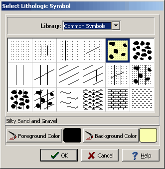
(The appearance of the form will differ slightly depending on if it is WinLoG or WinLoG RT)
The following information can be entered and edited on this form:
Library: This combo box is used to select the symbol library for the layer. When the arrow at the right is pressed a list will display the available symbol libraries. After a library has been selected, the symbols displayed in the tab will be updated.
Symbol: The symbol for the layer can be selected by clicking on one of the 18 symbols displayed for the current library. The selected symbol is highlighted with a blue border.
Foreground Color: This is the color to use for the shaded parts of the symbol. The foreground color can be changed by pressing the Foreground Color button. When this button is pressed a Color form is displayed. Using this form, a basic color can be selected or a custom color can be specified.
Background Color: This is the color to use for the unshaded parts of the symbol. The background color can be changed by pressing the Background Color button. When this button is pressed a Color form is displayed. Using this form, a basic color can be selected or a custom color can be specified.
In addition to the above, the symbols fill size, contact angle, line style, and splitting can also be specified by clicking the right mouse button on the symbol in the Symbol column. The Lithology form will then be displayed.
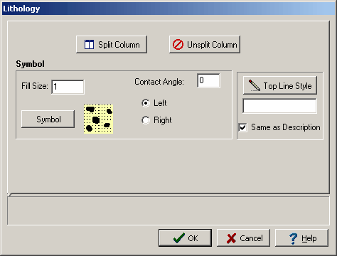
(The appearance of the form will differ slightly depending on if it is WinLoG or WinLoG RT)
The following information can be entered on this form:
Fill Size: The fill size is used to expand or condense the symbol before it is drawn on the log. The size of the symbol is multiplied by the fill size and then the symbol is drawn. For example, a fill size of 2 will result in the symbol being doubled in size. The fill size must be greater than 0.
Symbol: The symbol for the layer can be changed by clicking on this button.
Contact Angle: This is the contact angle for the top of the layer and can be used to indicate gradational or dipping contacts. A contact angle of zero is used to specify a horizontal contact. The contact angle must be between -80 and +80.
Left or Right: This is used to select whether the contact angle is specified from the left side of the symbol column or right side of the symbol column.
Top Line Style: The Top Line Style button is used to change the line style for the top layer boundary in the symbol column. If the bottom depth of the layer is specified this line style is also used for the bottom boundary. When the button is pressed, a Line Properties form is displayed. If the Same as Description box is checked, the line style will be set to the same as set in the Description tab for the layer.
Split Column: This button is used to divide the symbol column for the layer vertically and display two symbols for the layer. When the button is pressed the Symbol 2 part tab will be displayed on the form. This can be used to select a second lithology symbol for the layer. The symbol selected in the Symbol tab will be displayed on the left side of the column and the symbol selected in the Symbol 2 tab will be displayed on the right side of the column.
% Split: This is used to specify the percentage of the layer that is split between the two symbols. A 50% split would give create a layer using the left half of the symbol from the first symbol tab and the right half using the symbol from this tab.
Split Angle: This is used to specify the angle of the split between the first and second symbols. An angle of 90 degrees will show the symbols splitting vertically.
Split Line Style: This is used to specify the line style of the line between the two symbols. When the Split Line Style button is pressed a Line Properties form is displayed.
Unsplit Column: This button is used to remove the second symbol from the layer and display only one symbol. When this button is pressed the Symbol 2 part of the form will disappear.